Tuesday, June 1, 2010

Engines!

I apologize for the long delay, but I have been a bit busy.  So, here are some pictures of the engines being assembled.  I have all four done, but they aren't mounted on the wings yet.  They will have to wait until the wings are on the fuselage, which has to wait until I have finally decided what should go on the cargo floor.  Maybe I should just glue the tank down and close it up without any other cargo that no one will see anyway.

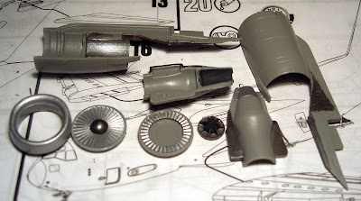
First up in the assembly process is the core section.  Here is one unassembled.  Towards the top is the aft section of the turbines, the lower right is the aft section of the fan blades.  The light silver part of the two halves roughly represents the core thrust reverser seam.


And here is a picture of all of the engine components.  The large pieces are the main engine cowling, the longer sections are the pylons that connect to the wing.  Reminds me of just how far forward they stick out from the leading edge.  Lower left is the "lip" of the intake, all polished and ready to vaporize some ice.  To the right is the front of the fan blades, then the core section as described above.


I can almost use this as an aide to teach jet engine theory.  It is the left half of an engine, pre-assembly.  You can see how the core fits into the main cowling, with the turbine section resting towards the back.  In front of that are the two halves of the fan section.  Finally, the intake rests at the far right.


On the top is a completed core section, roughly aligned with its counterpart below.  The darker paint represents not only the darkening from the engine exhaust, but also the titanium used to withstand the heat (up to 655 C).  The slot at the front of the engine is for the strake which I hadn't attached yet when I took this picture.  The only missing components from the engines are the EPR (and ice) probes inside the intake and the  various drain masts at the bottom of the engine.


We're pretty well recovered from our leave, so hopefully I'll have the time to get some more assembly done before I leave for a quick TDY right before my parents roll into town.

Friday, April 16, 2010

A Wing!

Sorry for the lack of posts, but our guest has meant less time to work on the model.  That and I've converted a couple 40K models to use the magnets as well.  Pictures will have to wait until tomorrow since it is too dark now.  But I got one wing assembled (sans winglet glued on).  I've only got one clamp, so I have to wait for this one to set before doing the other one.
There is a bit of a seam here between the top and bottom half of the wing, unfortunately.
A view from the font down the left side of the plane, wing held in place.  I put the kick window in this side too, but the hole you see at the bottom is the crew entry door.
A top view of the joint between the wing and body, and some spoiler panels.
Also, I finally found some sheet styrene so I can build some pallets.  I cut out three to put forward of the tank (two in the logistics rails, one in ADS).  The I built one into a rectangular box about 100 scale inches high, but I haven't decided what to do with the other two yet.  I wanted to make 4 or 8 barrels and put them on a pallet, but cutting 4-6mm circles out of plastic isn't easy, let alone bending the sides.  So that idea is probably scratched.  I might build a second tall box and paint it differently, then green stuff some random cargo for the pallet.  Then I can finally close up the cargo compartment.
As far as the 40K models mentioned above, I magnetized the arms on my dreadnaught so they are fully interchangeable.  Both of my wave serpents got magnetized turrets with little effort.  The most complex mod was magnetizing my predator's turret.  I cut out some styrene to fill the bottom of the turret so I can put a magnet inside.  Then I did pretty much the same thing in the main body.  This cuts visibility into my nicely painted compartment, but you can still open the rear hatch.  Then a magnet in both sides and it will stay in place nicely.  The top bolter gunner fits tightly enough it won't require a similar treatment.

Friday, April 9, 2010

Magnets and Tanks

Yesterday I got my order of 100 6mm x 1.5mm and 100 3mm x 1.5mm magnets.  They are nice and strong, and simply awesome for all sorts of hobby stuff.  The first thing I did with them was mount some in the turrets and bodies of my 5 Panzer IV tanks from Flames of War.

I also got my 1/144 scale M1A1 Abrams tank!  Here it is, for no apparent reason next to the panzer, even though they aren't the same scale.  They are both tan though.

Here it is next to the paper I was using to judge scale from the load planning post.  I think the size is pretty close.  You can see the tank a bit better now, it is impressively detailed.

It fits!  Granted, this is without walls and a ceiling but I don't think it will be a problem.  There won't be a lot of room to see past it though, so the pallets might not be so productive after all.

This is actually the back of the tank.  Because the turret is located forward of the center of the tank, the turret is rotated 180* backward for transport to reduce the overall length.

And a nice side view.  You can see the turret facing backwards here, and how much extra room there is foward and aft of the tank (remember the 4 pallet positions on the ramp).
Now that I have tank in hand I'll briefly look for some platic (or thin cardboard) to make some pallets and cargo before gluing down the tank and closing up the cargo compartment.  In the mean time, I'll probably build the engines.  As some of you may have noticed, Jake is now a contributer to the blog.  He will probably be putting up some of his Tau painting projects.

Wednesday, April 7, 2010

Gear Wells

I got the gear wells done finally.  Here you can see one assembled and one in pieces.
And here is the completed assembly attached to the outside of the inner wall.  The outer hull will go over this, forming the enclosed gear well.  The hole on the right is a troop door window.
I added the cargo straps on the wing box, magically transforming this into an ER jet.  The stripes are terrible, but you won't be able to see much more than the color...I hope.
Next came the massively compicated task of gluing the top and bottom halves of the horizontal stab togeather.  The staging lights on the bottom are a nice touch though.
I also put in some of the main body windows, like this CP kick window.  I used plain white glue to avoid the fogging that superglue causes for clear parts.
And finally, something to fly the plane with!  They are just toothpicks painted black, and are massivly over sized, but you should be able to see them through the cockpit windows at least.  If they look to big later, I can always rip them out.
Next step will be gluing the wings togeather and then I might have to pause for a bit to wait for the tank.  Oh well!

Tuesday, April 6, 2010

Step 4

Late day at work today, so no new work (gear pods half done still).  But here are some new pictures from yesterday.  First up are some pictures of the interior walls of the cargo bay.  The outer hull is actually two additional pieces that wrap around these two. 
Here are both sides.  The large gap on the right is the ramp/door, while the gaps in the middle are where the wing box/ER tanks are.
Here is a closeup of some of the sidewall seats (belts and buckles are molded into the plastic) and a troop door (handles here are freehand).  Loadmaster station is freehand as well.

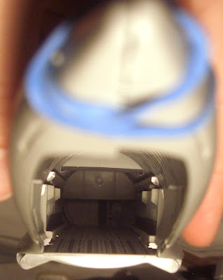
Next I did a fit test of the cargo bay with a rubber band.  It is the two walls and the cargo floor/flight deck.  The wing box sits nicely on top.  You can see where the inside of the gear pod will attach, and the crew entrace door up front.
Then I fit the outer hull over the cargo bay, again held in place with rubber bands.  The fit isn't great because of the band inside (I'll use tape if I do it again).  Luckily, the vertical stab is molded on in one piece!
Looking like an airplane, at least until I take it apart again.  This shot highlights the challenge that the windows will be.  A single piece of clear plastic will cover the cockpit there, and I will have to paint the roof and columns by hand.  Color matching will be very important, or I will have to paint the entire plane.  I'm confident you will be able to see a bit of the MFDs I painted on, so I will make some sticks from some toothpicks and just glue them to the floor.
So, will any of my work detailing the cargo compartment be visible?  Probably not.  But you'll be able to see a tank in there!  The bubble window into the crew rest area is plainly visible, even with the wing box in place.
Another view, without the outer hull on.
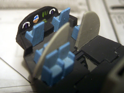
A better picture of the flight deck, no more work on it yet though.
And a preview for next time, the left side main gear struts.  I painted them on the sprue, which worked out a bit better than the nose gear. 
After I get the gear wells onto the inner hull I will have to wait on main hull assembly until I get my tank in the mail.  Although it should fit through the open ramp/door, I don't want to deal with positioning and securing it with the walls up!  I'll try to continue with other sub-assemblies though, and just keep them seperate until later.

Sunday, April 4, 2010

Load Plan

I mentioned last post that I had to cut some of the parts to get the door open.  The model has 3 basic configurations you can build it in.  The first is fully clean, airborne.  The next two are on the ground, doors open or closed.  I have a wooden C-17 already in flight, so my next thought was that I would build it with the gear and flaps hanging with spoilers up and maybe put it on a nice dirt base for a SPRO assault.  But the wings are solid, no options to put the flaps down.  The kit is a bit too expensive for me to destroy the wings in an attempt to drop the flaps, so I then got the idea that if it has to be on the ground I'll at least have it doing some work.  So I decided to find a 1/144 scale M1 Abrams tank and load that into the back!  I haven't found one locally, so I'm going to have to order it online.  I'm also planning on building a few pallets from plastic card to fill up the front some more.  Anyone know where I can find a 1/144 scale loadmaster?
Piece of paper in scale for an M1 Abrams (2.16in x1 in)

And here is a fake C-17 fully loaded with paper pallets!


Next up will be the cargo compartment walls, then the main gear pods.
~Trueborn

Steps 1-3

Official disclaimer: I am not using Revell colors for the model.  I'm aproximating them from the paints I already have based on some color codes I found online.  That and I'm taking a few liberties where I think I know better what the plane looks like.

The first step was to paint the flight deck.  Now, I've never built a model at this scale before, but I recal other cockpits that I've done being much more detailed (this is a difficulty 5 model).  This is the part of the model I'm most disapointed in.  Granted, the windos aren't that large so you probably won't be able to see in very well, but there aren't even sticks or throttles.  Also, the crew rest area is huge with no bunks.  I painted in some MFDs and MCDs on the center console. I'm looking for something about the right size to stand in for sticks.  Any ideas for a throttle quadrent?

The last thing I'm thinking of moding for this is the bunk bubble window (bottom center of this shot).  Currently it is just a bump on one side of the wall, but I'm considering drilling it out so you could actually look through the cockpit into the cargo compartment, except I don't have any idea if the sight line will work out.  Maybe I'll just paint it and the missing bunks dark blue to pretend they are the curtains.
Here is a view of the cargo floor and forward loadmaster station up the stairs.  Note the lack of a galley.
Here is a view from the top of the cargo floor and flight deck area.  The ramp has been cut off so I can leave it open.
And here is the belly, bottom of the ramp, and cargo door.  You can see them as a single piece in the last post, I had to cut them to get the door and ramp open.
And here is the nose gear and compartment, minus wheels.  Top of the picture is the nose, at the bottom of the strut you can see where the wheels will go.  I might put in the rub pads that stop the wheels from spinning if the front panel is close enough to the real thing.


Next post will be a quick one detailing the load plan.

~Trueborn

Initial Kit

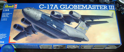
First useful post!  Here is the box the kit came in, as well as some of the random models sitting on my desk.

The kit is made by Revell, and Shawna found it for my at a local hobby store :)  Here is the instruction booklet.  Standard European 14 languages.

And finally, the sprues.  They are by far the largest I've ever seen.  Interesting mix of parts 16 inches long to 1/2 and inch.  All molded in a pleasent AF grey, so I won't have to airbrush the outside (which is good, since I don't own an airbrush!).

Next post will actually show progress.

~Trueborn

New Blog!

I've decided to start a blog detailing the construction of the 1/144 scale C-17A Globemaster III model I recently got. I will also probably include any other random modeling/painting projects I work on. By its nature, this will be very photo intensive.

~Trueborn